Plumbing Plan Reading, Blueprint Symbols & Schematics
The foundational educational resource for mechanical estimators: learn to decode P-series drawing sets, identify standard piping symbols, translate abbreviations, and correlate riser diagrams into accurate quantity takeoffs.
What Are the Core Elements of a Plumbing Blueprint Set?
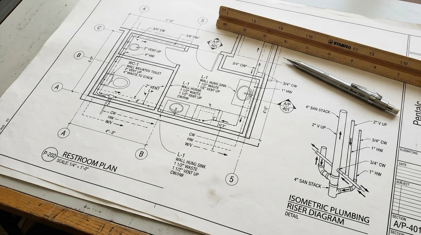
A complete plumbing blueprint set (P-Series) contains: 1) Cover sheet with symbol legend and general notes, 2) Underground civil tie-in drainage plans, 3) Floor rough-in and water distribution plans, 4) Vertical riser diagrams and 3D isometric schematics, 5) Plumbing fixture and equipment schedules, and 6) Standard engineering installation details.
Need quantities from your plumbing plans?
If you are preparing a bid, send the current plans, risers, fixture schedule, project location, and deadline. A takeoff request should specify the systems to measure and whether you need quantities only or a priced estimate.
Request a drawing-based plumbing takeoffThe 12 Core Blueprint Components Every Estimator Must Master
Accurate takeoffs require synthesizing information across every drawing component:
The engineer's Rosetta Stone: defines linestyles (dashed vs solid), valve icons, cleanouts, and unique project symbols.
Contractual stipulations governing pipe testing pressures, sterilization procedures, seismic bracing, and sleeve firestopping.
Shorthand tags used throughout the drawings (e.g., DCW, DHW, HWR, SAN, VTR, SS, RD, PRV, RPZ, FCO).
Distinct vector patterns isolating systems (e.g. solid heavy line for waste, dash-dot for hot water, dashed for gas).
Alphanumeric labels (P-1, WC-2, LAV-1) marking physical fixture locations on architectural floor layouts.
Dimension labels indicating pipe nominal size and gravity drainage slope (e.g., 4\" SAN @ 1/8\"/FT or 1/4\"/FT).
2D vertical schematic views illustrating stack pipe sizing progressions, vent terminations, and floor branches.
30° axonometric projections showing true 3D spatial routing of mechanical room headers and complex battery rough-ins.
Tabular matrix listing fixture manufacturers, model numbers, rough-in sizes, mounting heights, and carrier types.
Enlarged cross-sectional views demonstrating flashing rings, in-wall carrier anchoring, and grease interceptor baffles.
CSI MasterFormat Division 22 written manual that governs approved pipe wall thicknesses, joining, and valve rosters.
Formal amendments issued during the bidding phase that supersede original drawing sheets and specification clauses.
Essential Plumbing Blueprint Abbreviations
Standard shorthand terms universally adopted on commercial MEP construction plans:
| Abbreviation | Full Term | Engineering Definition |
|---|---|---|
| DCW | Domestic Cold Water | Potable cold water supply piping to fixtures |
| DHW | Domestic Hot Water | Heated potable water supply from water heaters |
| HWR | Hot Water Recirculation | Continuous loop piping ensuring instant hot water |
| SAN | Sanitary Sewer / Waste | Gravity drainage carrying blackwater and greywater |
| VTR | Vent Through Roof | Atmospheric vent pipe penetrating the building roof |
| RD | Roof Drain | Primary stormwater collection drain on roof deck |
| OD / OF | Overflow Roof Drain | Emergency secondary drainage set 2" above roof drain |
| CO / FCO | Cleanout / Floor Cleanout | Removable access plug for snake clearing of DWV lines |
| PRV | Pressure Reducing Valve | Mechanical valve regulating incoming water pressure |
| RPZ | Reduced Pressure Zone | High-hazard backflow preventer assembly with relief valve |
| WH | Water Heater | Commercial or residential potable water heating vessel |
| TP | Trap Primer | Device dispensing water to floor drain traps to prevent gas escape |
Moving from Plan Interpretation to Quantity Takeoff
Professional estimators follow a repeatable 6-step discipline to transition from reading drawings to measuring quantities:
Need an Expert Estimator to Read Your Blueprints?
Submit your construction drawings for an itemized digital quantity takeoff and turnkey bid preparation from certified mechanical estimators.